A Military DC to DC Power Converter transforms one direct-current voltage into another for demanding defense electronics. It helps radios, sensors, navigation units, displays, and embedded computers receive stable power. Unlike ordinary commercial converters, it must perform reliably during vibration, temperature changes, electrical noise, and limited maintenance access.
The design usually includes switching circuitry, magnetic components, filtering, protection, and thermal management. Input voltage may fluctuate when batteries discharge or vehicle systems change operating conditions. The converter must still provide clean, regulated output power. Efficiency matters because wasted energy becomes heat inside a sealed enclosure. Every degree can affect component life.
Small details matter.
Engineers often evaluate isolation, transient response, electromagnetic compatibility, shock resistance, and fault behavior. They may also review documented test results against applicable military or industry requirements. However, no single specification guarantees suitability for every platform. Installation, grounding, cable length, airflow, and load behavior can change real performance. That point is easy to overlook.
A reliable Military DC to DC Power Converter should therefore be selected through measured requirements, not impressive labels alone. Engineers need to confirm voltage range, output capacity, ripple limits, efficiency, cooling method, connector strength, and environmental ratings. Field experience can reveal problems that laboratory data misses. A connector may loosen after repeated vibration. A converter may run well on a bench but overheat in an enclosed vehicle bay.
This guide explains how these converters work, where they are used, and which specifications deserve careful review. It also considers practical trade-offs between size, efficiency, protection, cost, and long-term reliability. Some assumptions may need testing. That is normal in serious power-system design.
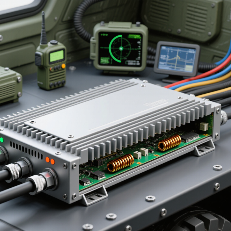
A military DC-to-DC power converter changes one direct-current voltage into another. Its purpose is practical: it lets radios, sensors, displays, and control computers share a vehicle or aircraft power system safely. A 28 VDC vehicle bus may need to supply stable 12 V, 5 V, or higher isolated outputs. The converter must manage voltage swings, electrical noise, vibration, and sudden load changes inside a compact enclosure.
Military standards define the electrical environment. MIL-STD-1275E specifies requirements for equipment connected to 28 VDC ground-vehicle power systems. MIL-STD-704F describes aircraft power characteristics, including 28 VDC and 270 VDC classes. These documents show why ordinary commercial adapters are often unsuitable. A converter may need input protection, galvanic isolation, electromagnetic compatibility, and controlled startup. Thermal design matters too. A small unit can become a hot metal block when airflow is limited.
Reliability testing should reflect field conditions, not only laboratory comfort. Defense environmental guidance commonly references temperature, humidity, shock, vibration, and altitude testing under MIL-STD-810H. Efficiency above 90% is a useful engineering target, but it is not universal. Higher efficiency still creates heat. That trade-off is easy to underestimate. In practice, engineers should verify derating curves, transient response, isolation ratings, and connector retention against the platform’s actual requirements. Standards provide a foundation, but they do not replace system-level testing.
| Data Dimension | Typical Information | Definition or Purpose |
|---|---|---|
| Product Definition | Power-electronic device that converts one direct-current voltage level into another | It enables equipment with different voltage requirements to operate from a shared military vehicle, aircraft, shipboard, or field power system. |
| Common Input Sources | Nominal 12 V, 24 V, 28 V, 48 V, or higher-voltage DC systems | The converter adapts available platform power to the voltage required by radios, sensors, navigation equipment, computers, displays, and other electronic loads. |
| Typical Output Range | Approximately 3.3 V to 48 V DC, depending on the application | Multiple output ranges support low-voltage digital electronics, embedded processors, communication equipment, and higher-voltage subsystems. |
| Conversion Function | Step-down, step-up, or input-to-output voltage regulation | A step-down converter reduces voltage, a step-up converter increases voltage, and a regulated converter maintains a stable output despite input or load changes. |
| Electrical Isolation | Non-isolated or galvanically isolated designs | Isolation separates the input and output electrical circuits, helping reduce ground-loop problems and limiting the transfer of faults or electrical noise. |
| Typical Efficiency | Approximately 80% to 95%, depending on topology, voltage ratio, load, and operating conditions | Higher efficiency reduces wasted energy, heat generation, cooling requirements, and stress on batteries or vehicle power systems. |
| Output Regulation | Commonly maintained within a few percent under specified operating conditions | Stable voltage helps protect sensitive electronics and supports predictable operation during changes in input voltage, temperature, and electrical load. |
| Power Capacity | From a few watts to several hundred watts; larger systems may exceed this range | The required power rating is selected according to the continuous load, startup demand, transient requirements, and system expansion margin. |
| Input Voltage Variation | Designed to tolerate specified fluctuations around the nominal platform voltage | This capability allows equipment to continue operating during battery discharge, generator variation, engine starting, or changes in the vehicle electrical bus. |
| Operating Temperature | Common ruggedized ranges include approximately -40°C to +85°C; the exact range depends on the design | Extended temperature capability supports operation in exposed outdoor environments, vehicle compartments, aircraft equipment bays, and other demanding locations. |
| Protection Features | Overvoltage, overcurrent, short-circuit, overtemperature, input undervoltage, and reverse-polarity protection | Protection functions help prevent damage to the converter and connected equipment during abnormal electrical or thermal conditions. |
| Electromagnetic Compatibility | Designed to control conducted and radiated emissions and withstand specified electromagnetic disturbances | Good electromagnetic compatibility reduces interference with radios, radar, navigation systems, sensors, and other mission electronics. |
| Mechanical Construction | Rugged enclosure with secure mounting, sealed or conformal-coated circuitry, and reinforced connections | The construction helps the converter withstand vibration, shock, dust, moisture, and other physical stresses associated with military platforms. |
| Cooling Method | Natural convection, conduction through the enclosure, forced air, or a combination of methods | The cooling method is selected according to power density, available airflow, enclosure constraints, ambient temperature, and platform installation requirements. |
| Typical Applications | Vehicle electronics, tactical communications, surveillance systems, unmanned platforms, avionics, naval electronics, and field equipment | These converters provide compatible and stable power to electronic subsystems operating from a common platform power source. |
| Reliability Objective | Continuous operation under vibration, shock, temperature changes, electrical transients, and limited maintenance conditions | High reliability is important because power-converter failure can interrupt multiple connected systems or reduce mission availability. |
| Compliance Considerations | Testing may address military environmental, electromagnetic, electrical-transient, and safety requirements specified for the platform | Applicable requirements depend on the installation, system architecture, procurement specification, and intended operating environment; no single standard applies to every converter. |
| Main Benefits | Voltage compatibility, electrical isolation, improved power quality, protection, reduced wiring complexity, and system integration flexibility | A military DC-to-DC converter allows modern electronic equipment to be integrated reliably into platforms with varying or electrically noisy DC power systems. |
Note: The electrical ratings and environmental ranges shown are representative engineering ranges rather than universal specifications. Actual performance depends on the converter design, installation conditions, load profile, qualification requirements, and platform power architecture.
It changes one direct-current voltage into another controlled voltage. A 28 VDC vehicle bus may provide stable 12 V or 5 V outputs. That keeps onboard electronics working during voltage changes.
Radios, sensors, displays, and control computers commonly use converted power. Each device may require a different voltage, current, or isolation level. One size rarely fits everything.
Military platforms can experience vibration, electrical noise, heat, moisture, and sudden voltage changes. A commercial adapter may fail inside a sealed vehicle enclosure. The laboratory may look kinder than the field.
Switching circuits rapidly control energy through inductors and transformers. Feedback sensors monitor the output repeatedly. A control circuit adjusts the switching pattern when input conditions change.
Galvanic isolation separates the input and output electrical paths. It can reduce ground-loop problems and limit faults spreading between devices. Isolation is useful, but it does not solve every system fault.
Review input protection, controlled startup, filtering, isolation, and electromagnetic compatibility. Check voltage range beyond the nominal value. Starting the engine can create a very different electrical condition.
Conversion above 90 percent efficiency still produces waste heat. A small converter can become a hot metal block with limited airflow. Check cooling paths, component spacing, and derating curves.
Testing should include temperature, humidity, shock, vibration, and altitude conditions. Engineers should also test moisture, electrical surges, and repeated startup cycles. Field behavior can expose weaknesses.
Compare full input range, continuous power, peak power, ripple, efficiency, and thermal limits. Review transient response and connector retention as well. A strong specification sheet still needs practical verification.
No. Standards create a useful engineering foundation. They cannot reproduce every vehicle layout, cable length, airflow path, or load change. Real testing remains necessary.
A Military DC to DC Power Converter is a specialized electronic device that transforms one direct-current voltage into another to provide stable, reliable power for defense equipment. It supports systems such as communication units, vehicle electronics, sensors, navigation equipment, and portable field devices, allowing components with different voltage requirements to operate from a common power source. The conversion process typically uses high-frequency switching, magnetic components, filtering circuits, and feedback control to regulate output voltage efficiently.
Designed for demanding environments, a Military DC to DC Power Converter must provide strong electrical performance, including high efficiency, low noise, voltage stability, and reliable load management. It may also require protection against overvoltage, overcurrent, short circuits, reverse polarity, and overheating. Compliance with applicable military standards helps ensure resistance to vibration, shock, humidity, dust, temperature extremes, and electromagnetic interference. When selecting a converter, engineers should evaluate input and output ranges, power capacity, efficiency, isolation, size, cooling needs, environmental conditions, and long-term reliability.